Root Causes of Weld Failures: Analysis Guide
Weld failures can lead to costly downtime, safety risks, and structural issues. Understanding what causes them is the first step to prevention. Here’s what you need to know:
- Common Issues: Cracks (hot, cold, fatigue), porosity, slag inclusions, lack of fusion, incomplete penetration, and distortion.
- Root Causes: Poor welding techniques, incorrect parameters, material problems (e.g., contamination, improper preheat), and environmental factors like wind or moisture.
- Analysis Process: Start with visual inspections, use non-destructive testing (NDT) when needed, document conditions, and compare findings against welding codes.
- Prevention Tips: Follow validated Welding Procedure Specifications (WPS), ensure proper welder training, maintain precise parameter control, and conduct thorough inspections.
Key takeaway: Weld failures are rarely caused by a single issue. A systematic approach to identifying and addressing underlying problems is essential to preventing them.
Common Welding Defects & How To Avoid Them
sbb-itb-6be7c12
Common Weld Failure Modes
Weld failures can manifest in various ways, each with its own causes and consequences.
Cracking
Cracking is often considered the most critical type of weld failure. As Welding Answers explains:
"Cracking is one of the most serious problems a fabrication shop can face. Unlike many other weld discontinuities, cracking is rarely cosmetic." - Welding Answers
Cracks are planar defects with sharp tips that concentrate stress, making them prone to propagation under load. The main types of cracking include:
- Hot cracking: Develops during solidification of the weld.
- Cold cracking: Often caused by hydrogen and may appear up to 48 hours after welding.
- Fatigue cracking: Results from repeated loading cycles over time.
Due to their severity, nearly all major welding codes - such as those from ASME, AWS, and API - enforce a zero-tolerance policy for cracks, regardless of size. Recognizing these defects is essential for proper weld failure analysis.
Beyond cracking, there are other defects that can compromise weld strength.
Porosity and Slag Inclusions
Porosity occurs when gas becomes trapped in the weld pool during solidification, leaving tiny cavities. Slag inclusions, on the other hand, are solid non-metallic residues from flux that get trapped between weld passes. Both are volumetric defects that weaken the weld's ability to bear heavy loads or withstand internal pressure.
One key difference: slag inclusions are exclusive to flux-shielded processes like SMAW, FCAW, and SAW, as these processes produce slag. In contrast, GMAW (MIG) welding doesn't create slag, so inclusions are not a concern. Welding codes like AWS D1.1 regulate these defects by size and density rather than imposing zero tolerance, but they can still pose serious risks in applications involving pressure or dynamic loads.
Next, we’ll look at flaws that compromise fusion beneath seemingly intact surfaces.
Lack of Fusion and Incomplete Penetration
Though often confused, lack of fusion (LOF) and incomplete penetration (LOP) are distinct issues:
- Lack of fusion: Occurs when the weld metal fails to bond with the base metal or a previous weld pass, leaving a planar void.
- Incomplete penetration: Happens when the weld doesn’t extend through the full thickness of the joint, leaving an unfused gap at the root.
These defects are particularly dangerous because they are often invisible to the naked eye. A weld might look perfect on the surface while hiding critical internal flaws. Both LOF and LOP are universally rejectable under major welding codes, as they can worsen under operational stresses.
"The teacher snapped it in two pieces in front of our eyes. We were all shocked because it looked like there was nothing wrong with the weld. He knew that the angle of penetration in the material was not proper, and the temperature settings were probably too low." - Emilie Peloquin, Executive Director of Global NDT Applications Engineering, Evident Scientific
Identifying these hidden flaws is critical for effective weld analysis.
Distortion and Warping
Distortion presents a different challenge. While it’s not a crack or void, it can still disrupt structural alignment and performance. Uneven heating and cooling during welding cause the metal to contract at varying rates, leading to warping, bowing, twisting, or angular misalignment.
Distortion is especially common when heat input is excessive or when welding sequences are unbalanced. While it may seem like a cosmetic issue, severe warping can introduce residual stresses that increase the risk of cracking or fatigue over time. It can also interfere with assembly by altering critical dimensions, leading to fit-up problems later on. Addressing both material and dimensional flaws is essential for accurate weld failure diagnosis and root cause analysis.
Root Causes of Weld Failures
Understanding why welds fail requires looking beyond the obvious defects to uncover the deeper causes. Most issues stem from how the weld is performed, the materials involved, or the conditions during fabrication.
Welding Procedure and Technique
Errors in welding procedures are a leading cause of defects. Using incorrect parameters - like current, voltage, or travel speed - can result in problems such as undercutting or lack of fusion. For thick or heavily restrained joints, not maintaining proper preheat or interpass temperatures is a major factor in hydrogen-induced cracking. Skipping steps like interpass cleaning can lead to slag inclusions, while poor joint preparation or fit-up increases residual stress, often causing cracks. Even small mistakes, like an incorrect arc length or electrode angle, can disrupt shielding gas coverage, leading to porosity.
"Most weld troubleshooting efforts fail for a simple reason: they focus on fixing the current weld, not the system that produced it." - Welding Answers
Neglecting proper qualification of Welding Procedure Specifications (WPS) or skipping welder performance testing (PQR) are shortcuts that often go unnoticed until failures occur under changing conditions. These lapses create a foundation for further issues, highlighting the importance of strict adherence to welding procedures.
Material and Consumable Issues
Sometimes, the base metal itself is the hidden culprit. For example, ASTM A572 Grade 50 steel with yield values of 62–63 ksi requires a minimum 300°F preheat for thick, restrained joints. A real-world example of this occurred during the fabrication of 5.5-foot-wide columns for a Manhattan high-rise. The shop used a prequalified WPS with a 225°F preheat - far below what the steel required - resulting in 1-inch-deep cracks. High-tensile-strength steels with a carbon equivalent above 0.40 are particularly vulnerable to hydrogen-induced cold cracking due to hard, brittle martensitic microstructures forming in the heat-affected zone.
Consumables can also play a role. Improper storage of low-hydrogen electrodes allows them to absorb moisture, introducing diffusible hydrogen into the weld pool. This can cause porosity or delayed cracking, which might not appear until 48 hours after welding.
"Table 3.3 [of AWS D1.1] is an available tool but it is up to the fabricator to determine if it satisfies the conditions required to make sound welds." - Elizabeth Mattfield, P.E.
Weather and Site Conditions
Environmental factors are often underestimated but can be a significant root cause. Wind, even a light draft, can displace shielding gas from the weld puddle, causing porosity - especially in outdoor or field jobs without proper windbreaks.
Cold temperatures speed up weld cooling, increasing hardness in the heat-affected zone and the risk of brittle fractures. Moisture is another common issue. Condensation on the base metal, high humidity, or moisture trapped in flux can all introduce hydrogen into the weld, promoting hydrogen-induced cracking. Surface contaminants like rust, oil, or cutting fluids add to these risks, making thorough cleaning and drying of fusion faces essential to avoid defects.
How to Analyze a Weld Failure
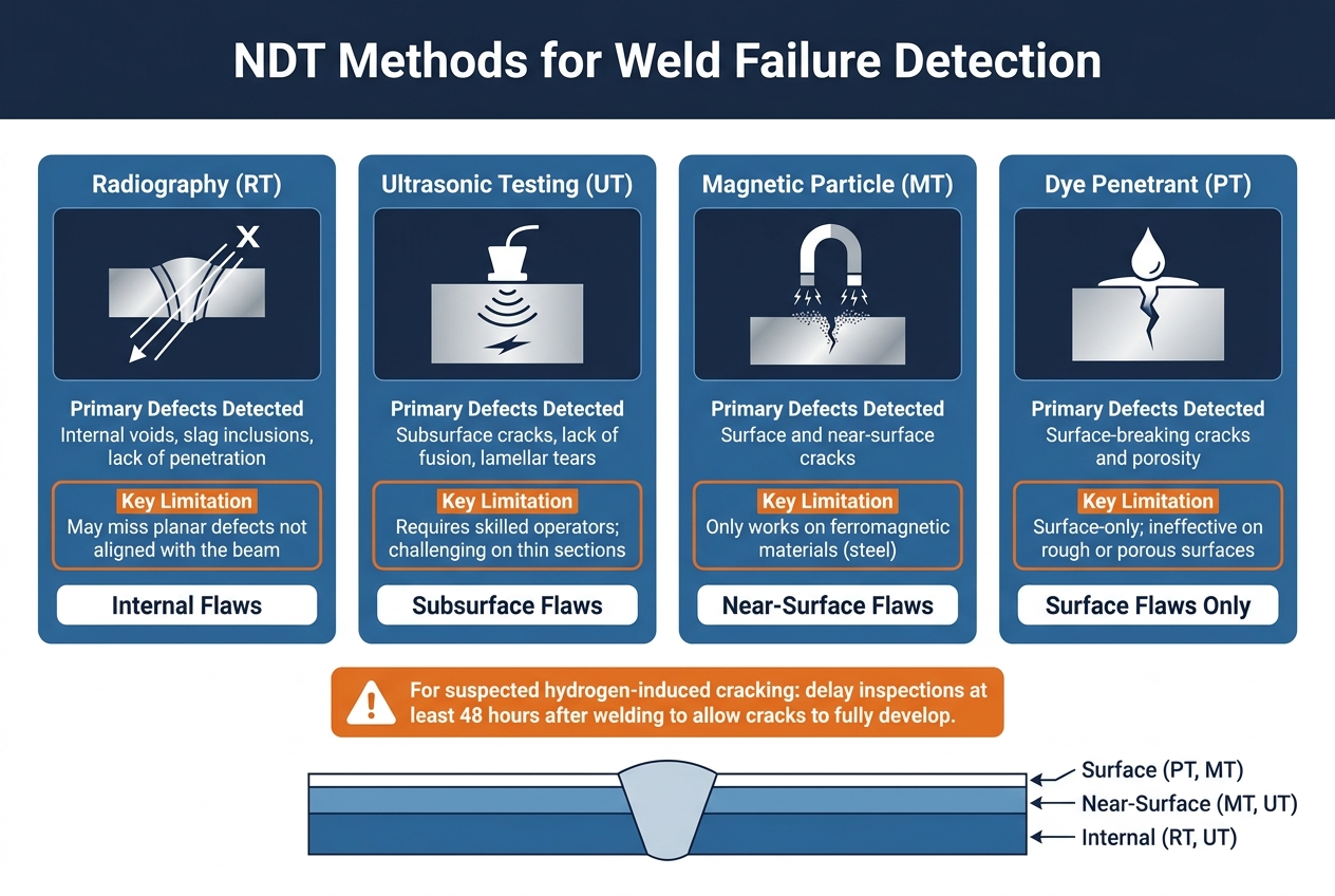
NDT Methods for Weld Failure Detection: A Quick Comparison Guide
Once you've identified the type of weld failure, a detailed analysis is critical to uncover the root causes. Jumping to fixes without understanding the problem often leads to repeated issues. A structured investigation should follow a clear process: inspect, document, and confirm. Here's a practical guide to analyzing weld failures.
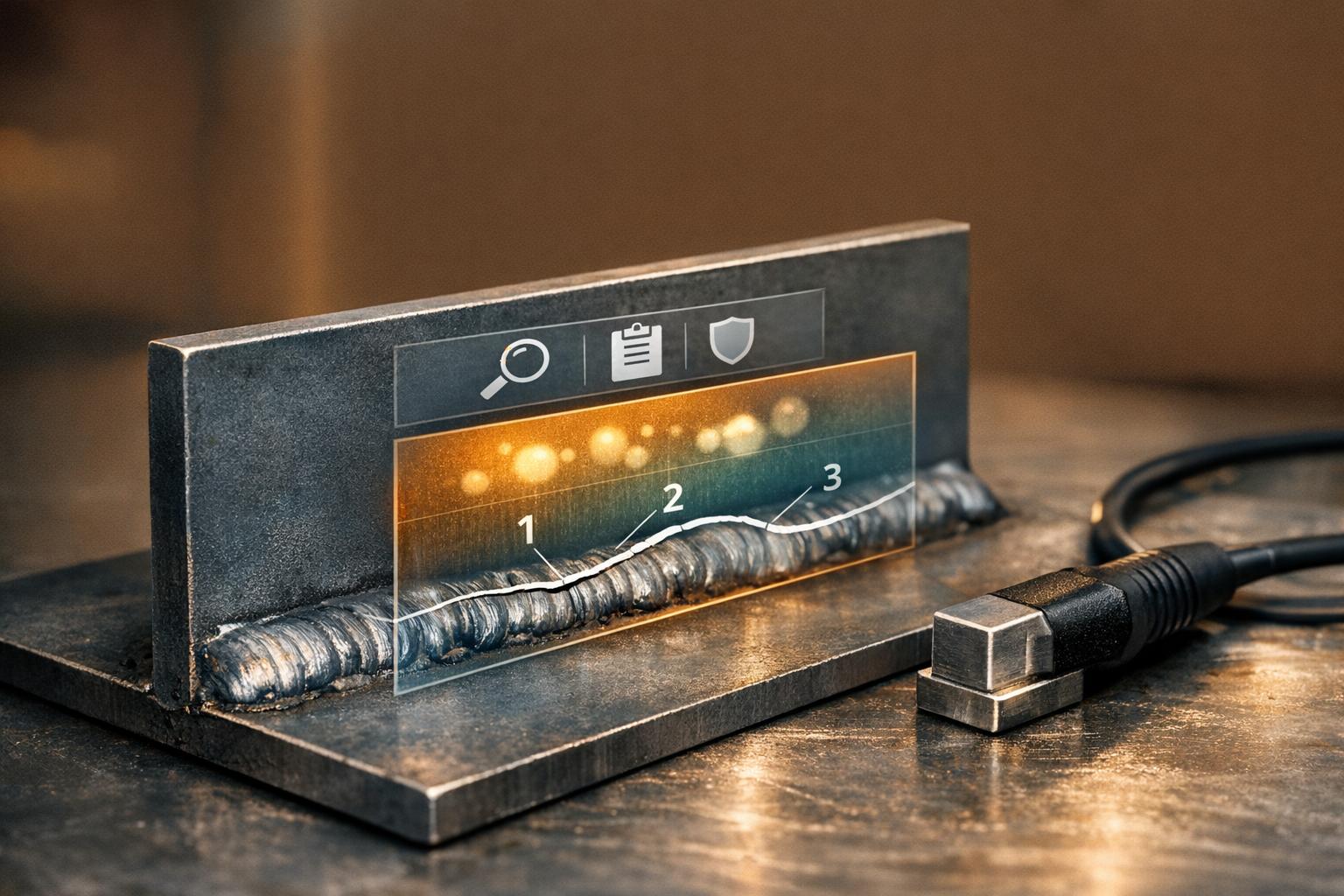
Visual and Non-Destructive Testing
Start with a visual inspection. Use magnifying tools to spot defects like undercut, overlap, burn-through, or surface porosity. For example, AWS D1.1 specifies that undercut depths must not exceed 1/32 in. (0.8 mm) for welds 1/4 in. and larger in statically loaded structures. Anything beyond this limit is a code violation and needs to be recorded.
If a surface inspection doesn't provide enough information, non-destructive testing (NDT) can help. Each NDT method targets specific flaws and has its own limitations:
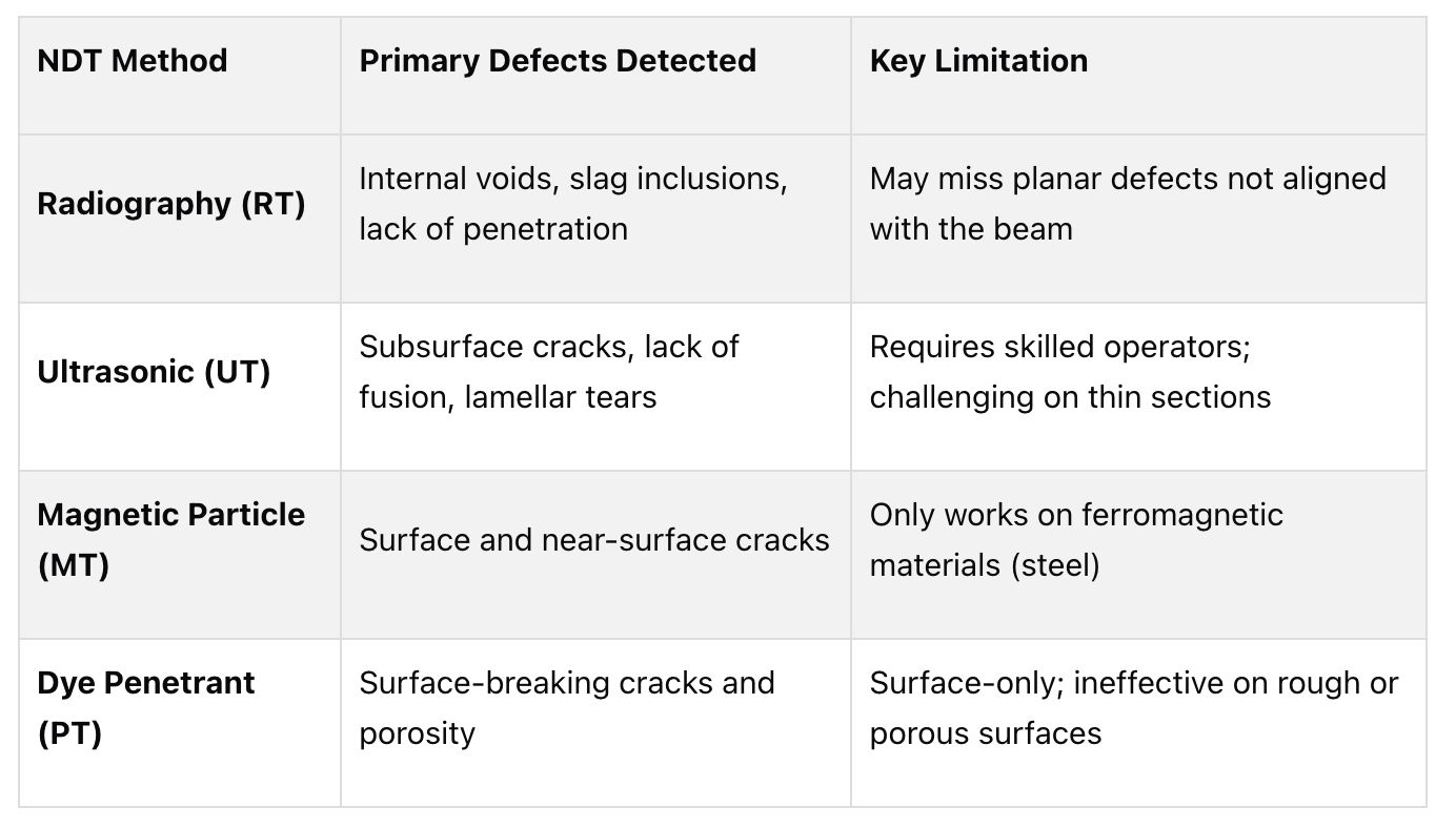 For suspected hydrogen-induced cracking, delay inspections for at least 48 hours to allow cracks to fully develop and become visible.
Recording Weld Conditions and Specifications
After inspections, detailed documentation is essential to identify the root cause. Complete records ensure that findings are based on evidence rather than assumptions. These records should include the Welding Procedure Specification (WPS), welder certifications, Material Test Reports, parameter logs, NDT reports, and Post-Weld Heat Treatment (PWHT) records.
Pay special attention to recording actual values rather than generic approvals. For instance, noting "2.5 mm root gap" provides more insight than simply marking "OK." Even if individual deviations fall within acceptable limits, their combination can still lead to failure. Industry data shows that pre-weld fit-up inspections alone can reduce NDT rejection rates by 30% to 50% on complex projects.
"A weld traveller... records the WPS number, welder ID, fit-up acceptance, preheat measurement, welding parameters, NDT results, and final disposition. Every inspection sign-off must be by name, certification, date, and time." - WeldFabWorld
Confirming the Root Cause
With inspection data and documentation in hand, compare everything against relevant welding codes - such as AWS D1.1 for structural steel or ASME Section IX for pressure applications. Use tools like the "5 Whys" method or a Fishbone Diagram to drill down into contributing factors instead of stopping at the first visible issue. Referencing standards is essential to ensure compliance during analysis.
For example, Atlantic Engineering Laboratories (AEL) investigated transverse cracks in 3.25-inch-thick column plates. Their forensic review of Mill Test Certificates revealed that the steel required a minimum preheat of 300°F, but the fabricator had only used 225°F. Combined with high joint restraint and the absence of post-weld heat treatment, the investigation concluded that multiple factors - not just one - caused the failure.
"Most often, a crack is produced in a 'perfect storm' of errors made during the design, procurement, and execution phases of fabrication." - Elizabeth Mattfield, P.E., Atlantic Engineering Laboratories
If destructive testing becomes necessary - such as metallographic sectioning or hardness testing to examine brittle microstructures in the heat-affected zone - ensure a strict chain of custody for all samples. Without this, the credibility of your laboratory results could be questioned, undermining the entire analysis.
How to Prevent Weld Failures
Understanding the causes of weld failures makes prevention much easier. Most issues stem from three key areas: how welding procedures are developed and followed, the level of training welders receive, and the consistency of inspections.
Procedure Qualification and Parameter Control
The first step in preventing weld failures is establishing a solid, validated welding procedure. A Welding Procedure Specification (WPS) provides the blueprint for consistent weld quality. It outlines crucial parameters - such as base materials, filler metals, joint design, voltage, and welding positions - so welders have clear, detailed instructions. A WPS is validated through a Procedure Qualification Record (PQR), which demonstrates that the procedure produces reliable, high-quality welds.
To qualify a procedure, test coupons undergo rigorous testing, including tensile, guided bend, Charpy impact, and hardness tests. These tests ensure the weld meets the necessary strength, ductility, and toughness before being applied in real-world projects. If an essential variable changes - like switching from SMAW to GMAW or using a new base material group - a new qualification is required.
"The sole purpose of welding procedures is to describe the details that are to be followed in the welding of specific materials or type of joint." - Iowa Department of Transportation
Two practical steps can help minimize weld failures: using stringer beads to control heat input and maintaining proper thermal control throughout the welding process. These measures reduce the likelihood of cracking in the heat-affected zone.
Welder Training and Certification
Even the best WPS is only as effective as the welder executing it. Welder Performance Qualification (WPQ) testing ensures that welders can produce acceptable welds under specific conditions. This testing covers the welding process, material group, thickness range, position, and joint type. Regular training is crucial to maintain skills and avoid bad habits.
"A weld can look good but still be unacceptable if it was made without the required procedure or welder qualification." - NTIA
Institutions like the Lincoln Electric Welding School and the Hobart Institute of Welding Technology, as well as union apprenticeship programs through organizations like the Ironworkers or Boilermakers, offer recognized training programs to develop and sustain welder proficiency.
Inspection and Quality Assurance
Inspection plays a critical role in ensuring weld integrity. It should happen at every stage - before, during, and after welding. Pre-welding inspections, such as reviewing Mill Test Certificates (MTCs), help verify the steel's properties and guide decisions on preheat and interpass temperatures.
During welding, routine checks of shielding gas delivery and equipment condition can prevent defects like porosity. Visual inspection by a Certified Welding Inspector (CWI) is highly effective, catching about 87% of surface and near-surface defects. However, no single inspection method is foolproof. Combining visual inspection with non-destructive testing methods, such as ultrasonic testing (UT) for planar flaws or radiographic testing (RT) for internal defects, enhances defect detection.
Adopting a structured quality management system, such as ISO 3834, formalizes these practices into a repeatable process. This approach shifts the focus from merely finding defects to actively preventing them.
At TDS Erectors & Crane Service, we adhere to these rigorous protocols to ensure weld integrity and the long-term durability of our structures. These measures are designed to maintain top-notch weld quality across all projects.
Conclusion
Weld failures are almost never the result of a single mistake. Instead, they arise from a combination of issues - whether in design, material selection, procedures, or execution - until the weak link gives way.
To truly address these failures, teams must adopt a systemic approach. Quick fixes might patch things up temporarily, but they won't tackle the root causes. The real game-changer is shifting focus from merely repairing defective welds to identifying and addressing systemic problems. This involves revisiting your Welding Procedure Specification (WPS), verifying mill test certificates instead of relying on assumed minimum specifications, and keeping detailed records of every corrective action to ensure solutions endure beyond the individual who implemented them.
Even a small crack or a single porosity cluster can reveal deeper procedural flaws that might lead to major failures in critical joints or thick plates. Every failure tells a story. Learn from it.
FAQs
How can I tell if a crack is hot, cold, or fatigue?
Hot cracks emerge when welds solidify at temperatures exceeding 1,000°C. These cracks often show up along the weld centerline or in the heat-affected zone (HAZ). On the other hand, cold cracks, sometimes called hydrogen-induced cracks, form after the weld has cooled to ambient temperature. They are typically associated with brittle microstructures, trapped hydrogen, and residual stress. Lastly, fatigue cracks develop over time during the component's use, caused by repeated cyclic loading combined with residual tensile stresses near the weld.
Which NDT method should I use for my suspected weld defect?
The most suitable nondestructive testing (NDT) method depends on where the defect is and its nature. For flaws on the surface, liquid penetrant testing (PT) is effective for nonmagnetic materials, while magnetic particle testing (MT) offers a quicker solution for magnetic ones. When it comes to internal defects, both ultrasonic testing (UT) and radiographic testing (RT) are excellent choices, though UT is often favored for its accuracy and safety. At TDS Erectors & Crane Service, quality is a priority on every project.
What records should I collect to identify the root cause of a weld failure?
To understand why a weld failed, it’s essential to collect and review detailed documentation. Key records to gather include:
- Site documentation: This involves notes and photographs that capture the failed weld and its surrounding area.
- Fabrication data: Important records such as Welding Procedure Specifications (WPS), welder certifications, inspection logs, material test reports, and consumable usage details are crucial for analysis.
- Process details: Information about the joint design, welding parameters, any post-weld treatments, and the weld's service history provides context for the failure.
By comparing these records to established welding codes, you can pinpoint the root cause while ensuring safety standards are maintained.
Related Blog Posts
Blogs, calculators, and other content on the TDS blog is for educational purposes only and does not constitute crane or rigging advice. For information specific to your situation, please contact us for an estimate or consultation.
Related Articles
Crane Lifting Capacity Calculator
Estimate crane lifting capacity by crane type, boom length, load radius, and angle. Fast results with safety guidance and input summary.

OSHA Rules for Powered Industrial Trucks
Summary of OSHA 29 CFR 1910.178: required operator training, daily inspections, maintenance, safe operation, and approved repairs for powered industrial trucks.

Construction Safety Checklist Generator
Create customized safety checklists for construction sites with our free generator. Select project type and tasks for OSHA-aligned lists in seconds!